The inner circuitry of load banks has a simple overall design with three main systems that keep the load bank running properly. By working closely with the control panel regulation, these three structures let the load bank build a load as needed. However, these systems also have safety features to dump the electrical load in an emergency. Understanding these circuits and their relationships to each other makes it easier to comprehend how a load bank works.
Three Primary Circuits in Load Banks
Load banks must create power loads for testing. To do this, the units have three types of circuits in them to power and regulate different functions – controls, cooling and load element. These load bank circuits ensure the safe operation of the device. Though complex when viewed on a load bank circuit diagram, these three systems have simple operation principles.
1. Load Bank Control Circuit
One of the three primary circuits powers the load bank controls. These controls, which may be digital or manual, regulate the operation of the other circuits. They also ensure the safest operation by triggering shutdowns during blower motor outages, load dumps, airflow errors or overheating. Some of the components connected to the control circuit are the main load application switch, blower starter, indicator lights and safety switches to turn off the system in emergencies or operational failures. However, on some load bank models, the safety switches have a separate circuit with its own fuse.
Digital Load Bank Controls
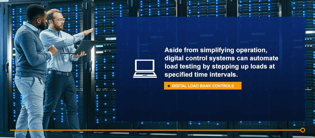
Though manual operator controls remain an industry-standard, digital load bank controls allow integration into control and communications systems. For instance, load bank digital control systems connect the device to a network for operation from a computer, tablet or remote control.
Aside from simplifying operation, digital control systems can automate load testing by stepping up loads at specified time intervals. Many digital operation systems integrate with manual controls, allowing the operator to use either for extra flexibility.
Remote operator controls, available on some models, readily display the three primary circuits of load banks by their available options. The operator can turn the main power on or off, start or stop the blower motor and apply stepped loads. Sensor indicators on the remote control panel also show the monitoring devices connected to the control circuit – airflow failure, blower status, power indicator and overheating.
Load Bank Circuit Breaker
The circuit breaker for a load bank will stop power going to a specific circuit in the case of an overload. While some load banks will connect to a circuit breaker for the main power sources, others will have switchboard connections to protect the components when producing a full load.
Whether a load bank has its own circuit breaker depends on how it connects to the main power system. Smaller portable units may use a spare circuit from a switchboard to provide the breaker needs. Permanent installations integrate their own disconnect switches or circuit breakers as close to the power supply as feasible.
The circuit breaker may trip or main disconnect fuses may blow if they do not have the correct sizes to match the load bank’s circuits. However, if a short in the main resistor for either the main input bus or the blower motor exists, the breaker will trip, or the fuse will blow. Also, shorts in the power conductors to the load bank can cause circuit breakers to trip or fuses to blow.
When problems arise with the circuit breaker, do not use the load bank until repairing the problem. These issues should start with an assessment of the circuit breaker or fuse trip ratings or sizing. If those elements are correct, evaluate the integrity of the load bank’s circuitry and the power going to it.
2. Cooling Circuit
The cooling circuit allows heat to dissipate from the load bank during operation. Load banks generate heat from the electrical currents they store and release. Once the control circuit triggers the cooling system’s blower motor to turn on, the cooling circuit takes over to keep the system running. With this cooling system, the load bank stays at a safe operating temperature.
When in use, the cooling system’s blower motor runs. However, the name does not necessarily indicate its action. This fan draws fresh air into the load bank from a cooling grille on the side. Then, it forces the air over the unit’s operating components, where the air draws heat away from the system. The heated air then leaves through the vent grilles opposite the intake opening.
To ensure the load bank’s proper operation, you need to leave enough space on the sides with the grilles for air movement. If the system becomes too hot from a lack of airflow or a damaged blower, the overtemperature switch will remove all load from the bank.
To avoid causing severe damage to the load bank, never operate it without the blower fan on and functioning properly operating. Make immediate repairs to blower fans or their motors if these parts fail before attempting to use the load bank again.
3. Load Element Circuit
The load element circuit regulates the operation of the load from the bank. This circuit includes the power resistors, main input load bus and load step switching. As with the control system, the load element circuit also has safety fuses to protect the elements.
Each load step has its own power resistor element that receives current as the load steps up. Typically, each load element will have its own fuse to protect against damage to the entire load element circuit. These resistor load elements combine in the resistor assembly frame. This framework holds the elements together while ensuring adequate cooling airflow through them.
The fuses for the elements provide an important safety feature. However, when one of these fuses blows, it can prevent the load bank from energizing a balanced load. An unbalanced load may also occur from a burned open or failed load element resistor. Replacing these damaged parts in the load element circuit can restore the bank’s full operation.
Contact Load Banks Direct for More About Our Industry-Leading Products and Services
Contact Load Banks Direct to find out about our products that fulfill the needs of multiple industries. With 20 years of industry experience, we can engineer solutions for almost any need. Additionally, we back our high-quality products with professional service and support. If you have the answers you need and want to get started, request a quote from us for your load bank solution.


We Are Here
To Help
Our team is here to support you and solve your power challenges. Connect with our responsive experts today to learn about our customized power solutions and products.